Lozenge system
Application
The lozenge system is a very elegant application of Zinc-Titanium for roofs and walls. It is used for covering large and small surfaces. The minimum pitch is 25°, or 18° when the vertex of the lozenge is soldered.
The standard NedZink lozenge system consists of small, uniform bent plates which hook onto each other. The most common form of a lozenge is the square, although the rhombus is also frequently used. In this brochure, the square lozenge will be discussed. In addition to lozenge, the names zinc tiles and zinc slates are also employed.
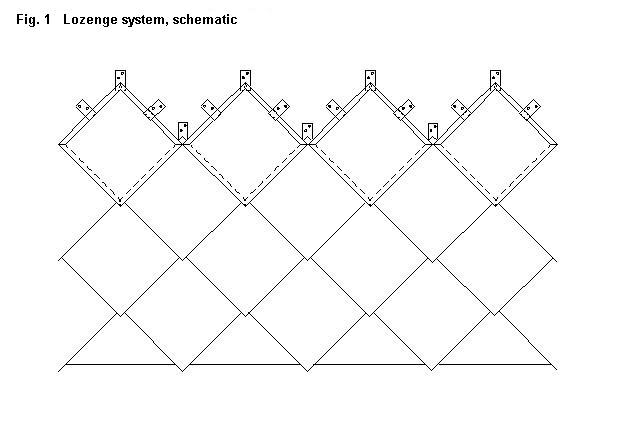
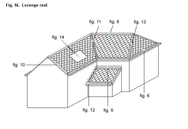
Lozenges provide a good solution for the cladding of moderately curved surfaces. When hooked together, the lozenges form a mosaic of uniform surfaces with vertical and horizontal diagonals. See photos figs. 17 + 18. Figure 1 is a schematic representation of the lozenge system. Fig. 16 shows a lozenge roof with references to detail drawings.
The Lozenge Roof
Specifications of standard components
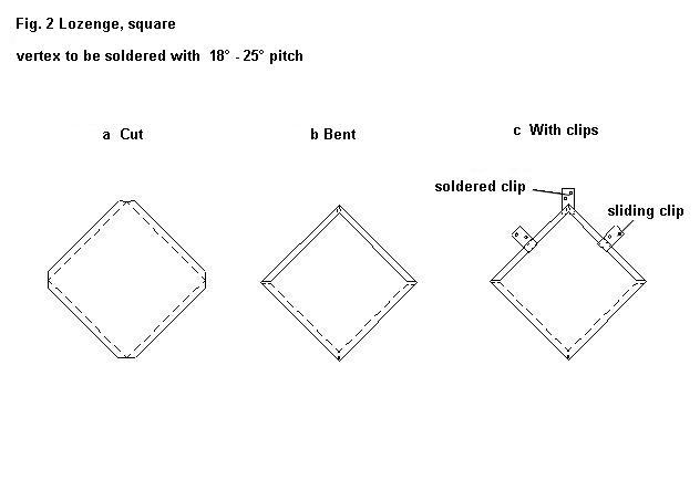
Standard lozenge, square (figs. 2a and 2b)
|
Lozenge size 450 x 450 mm 280 x 280 mm 200 x 200 mm |
Cutting size 500 x 500 mm 330 x 330 mm 250 x 250 mm |
Number/m2 approx. 5.6
approx. 15.3 |
|

Material thickness: 0.80 – 1.0 mm
The vertex of these lozenges have not been soldered and no fixed clips have been soldered.
The table in fig. 7 shows the relationship between material thickness, lozenge size, number of clips and roof height.
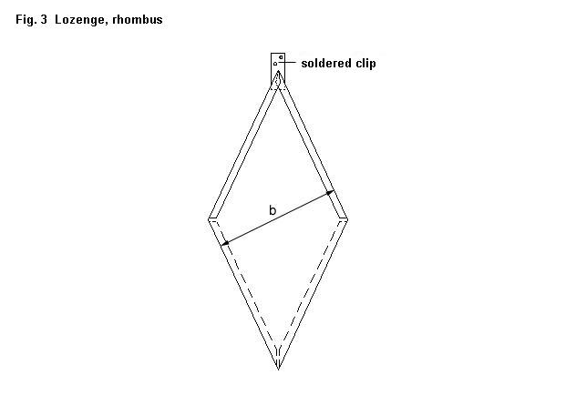
Standard lozenge, rhombus, vertex 50? (fig. 3)
|
Lozenge size width “b” 200 mm 250 mm 280 mm |
Cutting size
250 mm 300 mm 330 mm |
Number/m2
25.6
15.3 |
|

Lozenges with soldered fixed clips (fig. 2c) and soldered vertex can be supplied on request.
Pitches between 18? and 25? require soldered lozenge with soldered vertex. Lozenges in other sizes can be supplied on request.
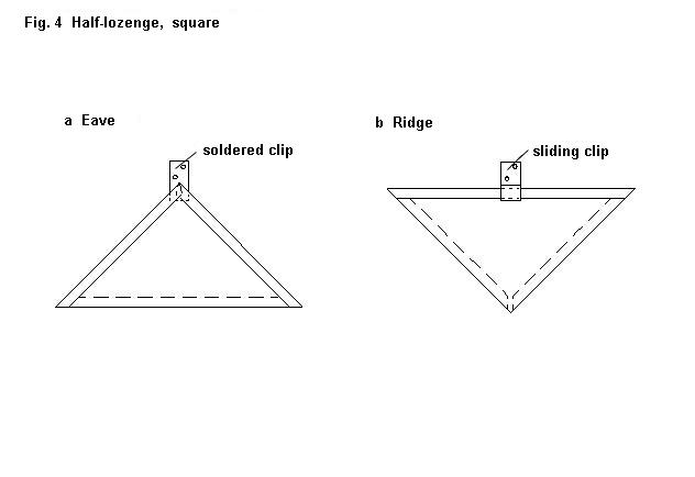
Standard half-lozenge, square (fig. 4)
|
Fig. 4a shows the half-lozenge for eaves abutment. Fig 4b shows the half-lozenge for ridge abutment. Sizes and thicknesses are the same as with whole lozenges. With a “top” half-lozenge, both a sliding clip and a soldered clip can be used. |
|

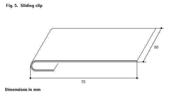
Sliding clip, 70 x 50 mm. (fig. 5)
Material thickness same as for lozenge. The sliding clip functions as a support clip. These support clips can be made by the fitter.
Soldered clip (fig. 2c)
50 mm width. Length approx. 100 mm, depending on location and space for fitting onto the base.
The clip can be made by the fitter and soldered to the lozenge.
Profiles
The dimensions of eaves profiles, attachement profiles, etc., will depend on the on-site dimensions; profiles can either be made by the fitter or supplied custom-made in 3 metre lengths.
Substructure
The lozenge roof must be fully supported by timber, preferably of rough, unplaned boards, 23-25 mm thick and not tongue-and-grooved. With pitches up to 40?, the boards may be no more than 10 mm apart. Above this angle, the timber boards may be spaced up to 10 cm from each other, so long as sufficient wood is always available for fixing the clips.
Ventilation: Roofs with thermal insulation must have a ventilated cavity permitting free circulation of external air beneath the timber boarding. See NedZink Advice TZ 5.
Assembly
The following description concerns the assembling of lozenges with soldered clips on the vertex and two support clips on the upper sides. The clips are to be fixed to the timber boarding with stainless steel or galvanized steel nails or screws.
The lozenges are mounted from eaves to the ridge.
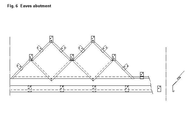
Eaves abutment
An eaves profile is first mounted (use a wire to place the clips for this). Hook the bottom half-lozenges (fig. 4a) onto this and then continue with whole lozenges (see fig. 6).
Marking: Lozenges are mounted with a small degree of play and marking is necessary to achieve a straight-line pattern. Begin marking from the centre of the roof surface by applying chalk lines on every third lozenge.
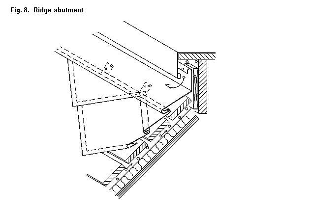
Ridge abutment
It is preferable to ensure that half-lozenges (fig. 4b) can be used for making a ridge connection. When this is impossible, the lozenges must be cut to the desired size and the top side must be bent over. These partial or half-lozenges are to be provided with sliding clips or soldered clips for mounting on the timber boarding. Subsequently finish with the top profile. Fig. 8 shows an example of ridge abutment.
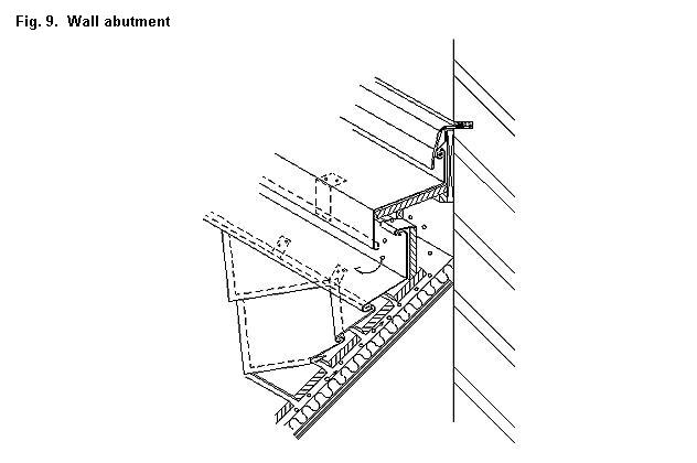
Wall abutment (see fig. 9)
Connections with walls are carried out in similar way to the ridge abutment.
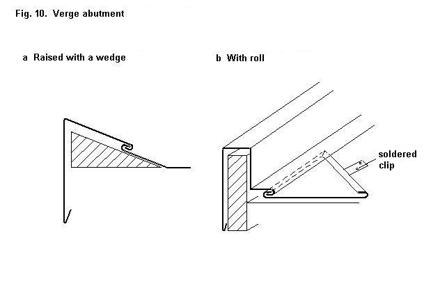
Verge abutment
To begin with there is an elegant finish, requiring the edge of the roof to be raised by means of a wedge-shaped beam (see fig. 10a). Another method is to finish with a verge roll (see fig. 10b).
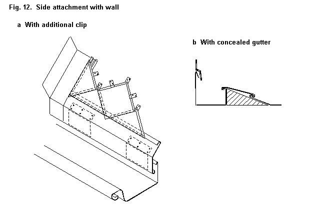
Side attachment of the roof to wall. Fig. 12a shows the side attachment by means of a zinc profile with additional clip. The straight up-stand of the zinc profile against the wall must be at least 10 cm high. Fig. 12b shows the concealed gutter method.
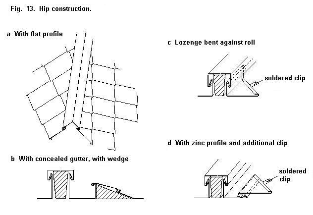
Hip construction
The hip rafter can be covered in a number of ways (see fig. 13).
Fig. 13a shows a method using a flat profile which is attached to the folded hooks of the lozenges. Fig. 13b shows the concealed gutter construction, which employs a roll placed on the rafter. This is also the case in figs. 13c and 13d. In fig. 13c, the lozenge has been bent against the roll. Ideally, this should be done before placing the roll on the hip rafter. Fig. 13d shows the method using a zinc strip with additional clip.
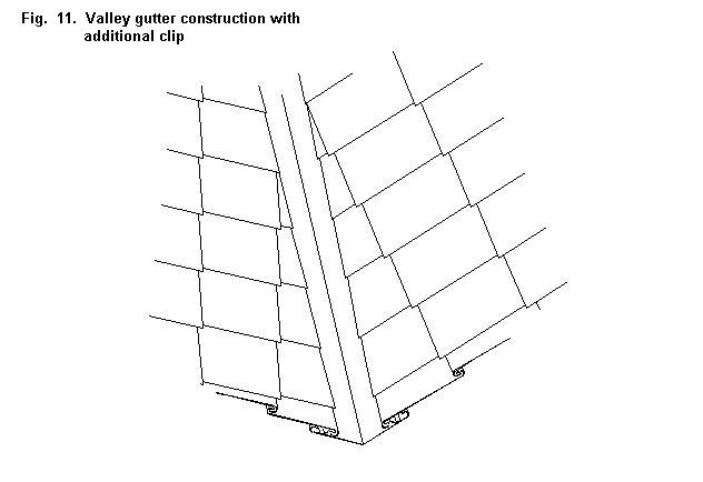
Valley gutter
The valley gutter is provided with a continuous additonal clip for hooking the lozenges (see fig. 11).
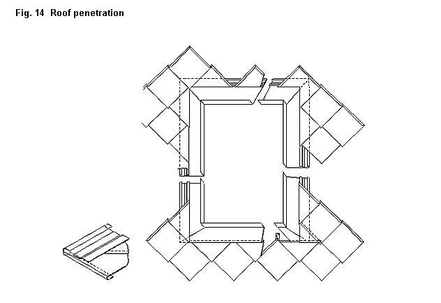
Roof penetration
A roof penetration requires the techniques used for ridge abutment, verge abutment and eaves abutment (see fig. 14).
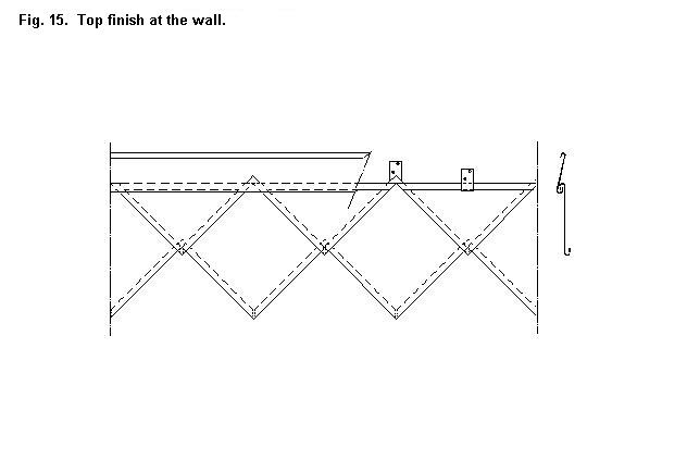
Facade cladding
The lozenge system works extremely well for facade/wall cladding. Assembling and connections are as with the lozenge roof. Fig. 6 shows the base connection, in which the base profile does not need to be bent in accordance with the pitch. The top finish is shown in fig. 15. Connections with windows are as in fig. 14. Although lozenges can also be used to cover very large surfaces, they are especially suitable for small roof surfaces with high pitch and for walls and sides of dormer windows. Small surfaces of course demand adapted lozenge sizes.
Consult the table in fig. 12 to calculate the distance between the clips for different bay widths and roof heights.
Fig. 7 Material thickness of lozenge and number of clips dependent on roof height and lozenge size.
|
Roof height |
Number of clips per m² |
Lozenge dimensions (cutting size) |
|||||
|
to 330 x 330 mm |
330 x 330 mm to 400 x 400 mm |
400 x 400 mm to 500 x 500 mm |
|||||
|
Material thickness* and number of clips per lozenge |
|||||||
|
Material thickness |
Number of clips |
Material thickness |
Number of clips |
Material thickness |
Number of clips |
||
|
0 – 8 m -inland -coast |
6 6 |
0,80 0,80 |
1 1 |
0,80 0,80 |
1 1 |
0,80 0,80 |
3 3 |
|
8 – 20 m -inland -coast |
6 8 |
0,80 0,80 |
1 1 |
0,80 1,00 |
3 3 |
1,00 1,00 |
3 3 |
|
20 – 100 m -inland -coast |
8 8 |
0,80 1,00 |
1 1 |
1,00 1,00 |
3 3 |
1,00 1,00 |
3 3 |
* Advice relative to lifetime and load.
