Roll Cap system
The Roll Cap System for covering roofs and facades
The Roll Cap System
Applications
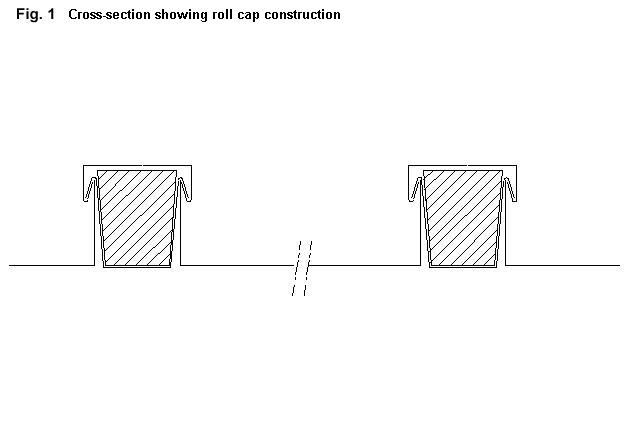
The roll cap system is suitable for large and small roofs with a pitch of at least 3?, and as a facade cladding. The standard roll cap roof made with NedZink Zinc-Titanium consists of zinc bays with upstands on both sides and separated by trapezoidal wood rolls. Zinc cappings are used to cover these wood rolls. This gives the roll cap roof is characteristic and robust appearance. Figs. 1 and 2 show a cross-section through the roll cap construction. The thickness of the zinc-titanium depends on the width of the bays and the height of the roof (see table in fig. 3).
The Roll Cap Roof
Specification of standard components.
|
Standard roll cap bay
width
lenght material thickness |
(fig. 4)
maximum 890 mm with 2 upstands
each 55 mm high. 3000 mm 0.80 – 1.0 mm |
|
|
Standard roll capping cross-section length material thickness |
(fig. 5) 65 x 25 mm 3000 mm 0.80 – 1.0 mm |
|
|
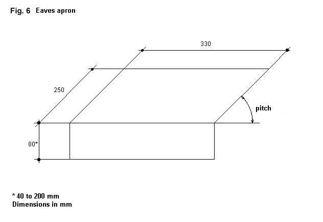
Eaves apron width material thickness The eaves apron is prepared by a sheetmetal worker |
(fig. 6) 330 mm as for roll cap bay
|
|
|
Zinc sheet clips width lenght material thickness |
50 mm > 220 mm as for roll cap bay
|
|


These clips are produced by a sheetmetal worker. The length must have a little excess, so that it
can be cut to the exact size during fitting (see also section headed 'Assembly').
|
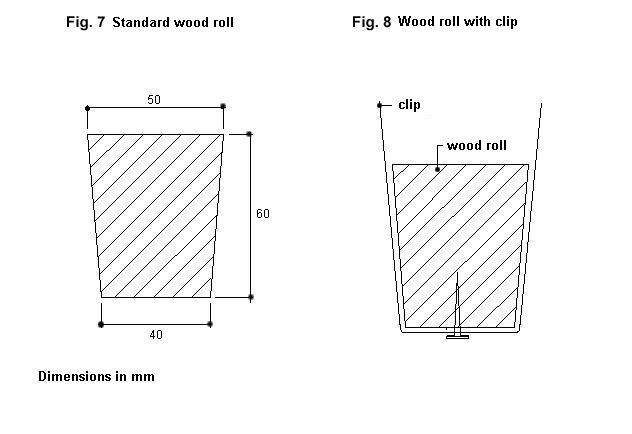
Wood roll (fig. 7)
Obtainable from timber merchants. |
|

Special requirements.
Connection profiles and non-standard cappings and roll cap bays may be supplied on request.
Substructure
The roll cap roof must be fully supported on timber boarding, preferably made of unplaned boards
(not tongue-and-grooved), 20-25 mm thick. Where the pitch of the roof is less than 40?, these boards
are assembled up to 5 mm apart. If the pitch exceeds 40? then the boards may be spaced further
apart: up to 10 cm. Joints between zinc bays must always be supported by boards.
Ventilation: Roofs with thermal insulation must have a ventilated cavity permitting free circulation of
external air beneath the timber boarding. See NedZink Advice TZ 5.
Assembly
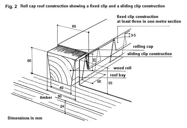
The clips must be attached to the wood roll as shown in fig. 8. The number of clips and their maximum distance apart are given in the table in fig. 3. The wood rolls are then carefully fitted to the timber at the marked points, with the narrow side downwards, preferably with galvanized steel screws. The distance between the wood rolls must be checked using a roof bay or a template.
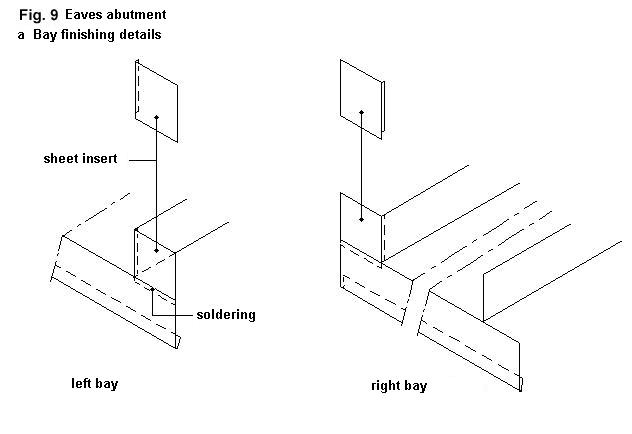
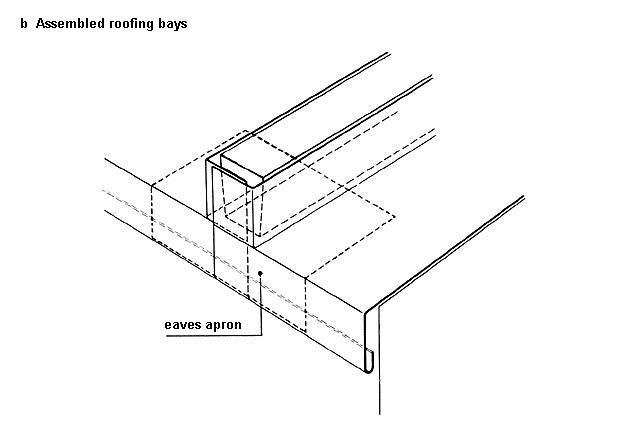
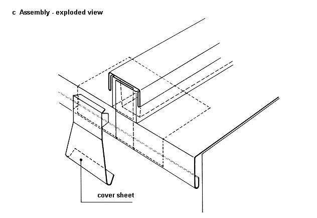
The eaves apron for engaging with the first roof bay are pushed between the wood roll and the timber and nailed down or screwed in place (see figs. 9b and 9c). The eave aprons must be correctly aligned.
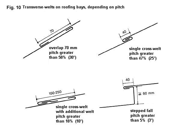
The first roof bay is hooked into the eave apron. The lower edges of this first bay is bent to the correct angle for the roof pitch. The selected length of the first bay is frequently 1 – 1.5 m. This bay, together with the soldered sheet insert, can be produced in the workshop in advance. Figs. 9a, 9b and 9c illustrate how the bays are finished and assembled at the eaves. The next bay up is then fitted, if more than one bay is required between the eaves and the ridge. The bays must be joined with a transverse welt as shown in fig. 10 or with a soldered joint. A bay consisting of a single length or several lengths soldered together must not exceed 10 m in length to allow for thermal movement.
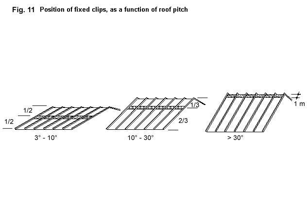
Fixed clip constructions are required, so that the bays do not slip down. The section at which these are fitted depends on the pitch of the roof (see fig. 11). There should be at least three of these fixed clip constructions in this 1 metre section of the bays as shown in fig. 11. An incision of approx. 3 mm is made in the upstand and the zinc is cut away at an angle (see fig. 2). The clip can then be turned over into this gap, thus preventing the zinc bay from slipping downwards. The remaining clips used are then sliding clips.
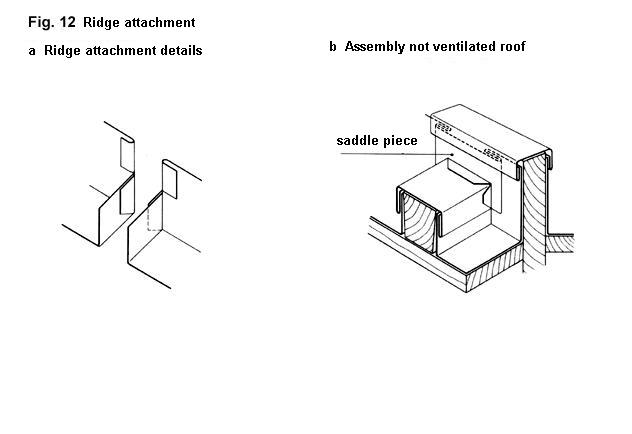
Ridge attachment (see figs. 12a and 12b). To begin with, the upper end of the bay must be formed as shown in fig. 12a, after which this bay is layed in position. The top bay which meets attached to the ridge can also act as an adjustment bay with a length of 1 – 1.5 m and this can be prepared in the workshop.
Connection to a hip roll is carried out exactly as for the ridge attachment, although in this case the connection is splayed.
Fitting the roll capping. Firstly all the clips should be turned down over the bay upstand and cut to a length of 22 mm from the upper edge of the roll. This is done to allow the roll cap to be pushed upwards. The roll cappings are then pushed up from one clip to the next. The point at which the roll capping is secured to the wood roll depends on the pitch of the roof (see fig. 11). The cappings are soldered together up to a maximum length of 10 m. The saddle piece is then soldered to the capping at the ridge (see fig. 12b).
At the eaves the capping is finished as shown in fig. 9c. A stop end is soldered to the roll capping and engaged with the eaves apron. This stop end should never be soldered to neighbouring bays. The same applies to bays laid alongside one another.
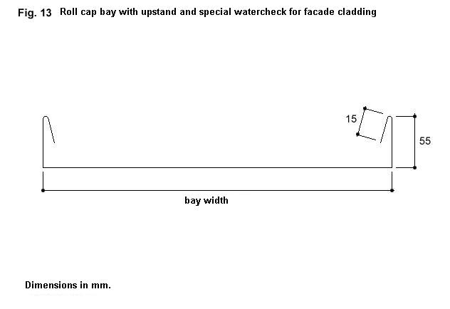
Façade cladding
A ventilated cavity is also required for this. The two upstands of the bays must have a special weather check for façade cladding applications (see fig. 13).