Quantity of rainfall.
Theoretical results show that in the Netherlands the maximum rainfall intensity at our geographical width is 540 – 600 (l/s)/ha). If the rainwater-drainage system of a building or house is based thereon then a rainwater-drainage system will never overflow. Within the standardisation the question has been raised if it is realistic that the costs of the size of a gutter for such a heavy rainfall intensity offset the inconvenience of a rare overflow.
It should be taken into account that the capacity of the public sewer will not be sufficient.
It is expected that once every 5 years the rainwater-drainage system may overflow, which is considered acceptable. This risk entails a rain intensity of 0.03 (l/s)/m² or 1.8 (l /min)/m².
The quantity of rainfall on a roof surface is determined by the effective roof surface in m² to be multiplied by the rain intensity (i) l/min. The dimensions of the rainwater-drainage system can be calculated by means of this quantity of rainfall to discharge per unit of time.
Calculation of the dimensions.
In the calculation of the rainwater-drainage capacity of a roof the dimensions of the rainwater downpipes and the number of rainwater downpipes are determinable. The choice for the (standard) gutter is to be made on the basis thereof. The standards NEN 3215 and NTR 3216 serve as guideline for the calculations.
The rain load
Determination of the quantity of rainfall (Qh) on a roof is made with the formula:
Qh = ( α x i ) x ( ß x F ) formula 1
Qh = the rainwater load in litres/minute (l/min.)
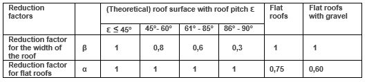
Table 1 Reduction factors for determining the load for rainwater downpipes at a
rain intensity (i) of 1.8 (l / min)/m²
Roof examples see figs. 1 and 2.
α = the reduction factor for the rain intensity for flat roofs
α = 0.60 flat roof with ballast of gravel
α = 0.75 for the other flat roofs
As flat roofs discharge the water at a slower pace, for all other cases (therefore all pitched roofs)
applies α = 1,
i = rain intensity and is 1.8 (litre / minute)/ m²
ß = reduction factor for the roof width is determined by the pitch of the roof
F = surface of the roof
The roof surface “F”
Figures 1 and 2 show different roof forms.
Determination of the roof surface “F”
The roof surface is determined by the product of the length (l) and the effective width (b) of the roof surface. The effective width is determined by the reduction factor ß.
Effective width of the roof and the reduction factor ß
The roof pitch ε determines the reduction factor ß. Walls also contribute to the discharge of rainwater
( ß = 0.3). It is indicated in the standard that no horizontal projection is applied. Table 1 gives the reduction factors for the various roof pitches.
Reduction factor α for flat roofs
For flat roofs the discharge of the rainwater to the roof outlet is slowed down. To this end, the rain intensity (i) of 1.8 (l/min)/ m² is multiplied by the factor α. See table 1.
The reduction factors α and ß are summarised in table 1.
Total quantity of rainfall Qh can now be determined by formula 1.
Determining rainwater downpipe.
The number of rainwater downpipes (n) must first be determined. The quantity of rainwater to be discharged in l/min is known from formula 1.
Prior conditions:
- number of rainwater downpipes per roof gutter length, see table 2.
- number of rainwater downpipes per m² roof surface, see table 3.
Table 2.
Min. number of rainwater downpipes per roof gutter length.

Table 3.
Number of roof outlets per roof surface.
The number is first determined by the structural design.
|
Roof surface |
Number of roof outlets |
|
<100 m² |
min. 1 |
|
>100 m² |
min. 2 |
For flat roofs:
Distance between 2 roof outlets must be limited from 10 to 20 metres. Place the roof outlet at
least 1 metre from the corner of the flat roof.
The quantity of water to be discharged per rainwater downpipe is “Qh : n” in l/min.
(n) = number of outlets.
Table 4 shows the choice of the accompanying smallest
standard roof gutter.
Depending on the circumstances the number of rainwater downpipes can be increased.
Gutters larger than the required minimum dimensions can always be applied.
The roof gutter must lie of course on slope and be installed from low to high.
For more information on the installation of roof gutters and rainwater downpipes, see NedZink Advice TZ1.
Arithmetical examples
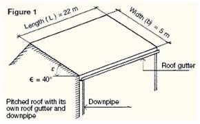
Example Figure 1
Dimensions.
(L) = 22 m, (b) = 5 m, Roof pitch ε = 40°
Single roof α = 1 and ß = 1, see table 1
Calculating the quantity of rainwater
Qh = α x i x ß x F
= 1 x 1,8 x 1 x (22 x 5)
= 198 l/min.
Number of rainwater downpipes:
Prior conditions,
- number of roof outlets per roof surface:
Roof surface (F) = 110 m2 => min. 2 rainwater downpipes, see table 3 - number of rainwater downpipes per roof gutter length:
Gutter length 22 metres => min. 2 downpipes Ø 80 mm, see table 2. (Expansion device required).
Choice of rainwater downpipes:
2 rainwater downpipes => 99 l/min => table 4 => Ø 80 mm
Choice of roof gutter is box gutter B37 or suspended
gutter M37, see table 4 (37 indicated the developed width in cm.).
Tabel 4
|
Max. quantity Rainwater Qh in l/min |
Ø Downpipe |
Min.cross-section (A) of the gutter |
Smallest type |
117 |
80* |
79 |
B37 or M37 |
210 |
100* |
125 |
B44 or M44 |
338 |
120* |
181 |
B55 |
* standard rainwater downpipes
** B = box gutter 37/44/55 = developed width in cm.
M = suspended gutter
The outlet piece for a rainwater downpipe has an inner diameter (di) that is at least 4 millimetres
smaller than the nominal size of the rainwater downpipe. This inner diameter of the outlet piece
determines the inflow capacity of the rainwater downpipe.
